Severe Structural Vibrations in Ocean-Going Vessel Refrigeration Plants
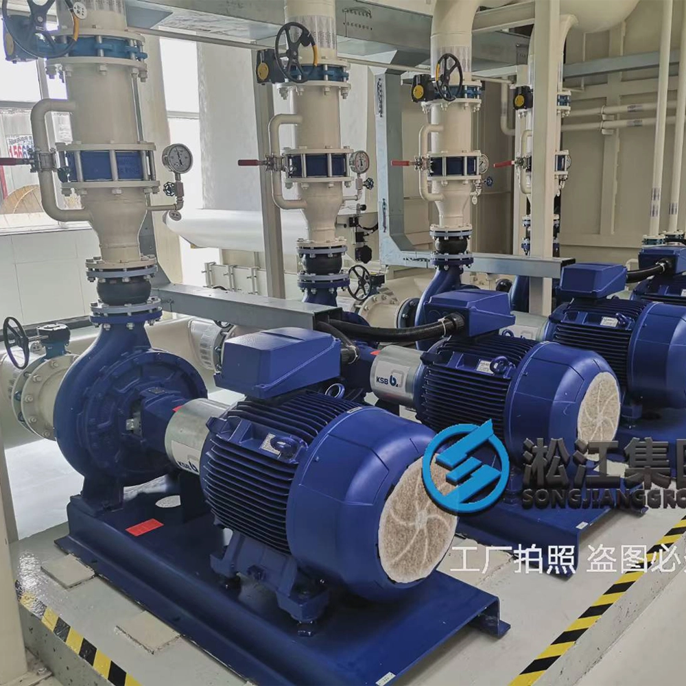
- Vessel HVAC Lines & Maritime Chiller Networks: In ocean-going vessels and offshore marine structures, centralized marine chiller units and maritime HVAC networks maintain critical habitation temperatures and cargo cold chain reliability.
- Engine Room Vibration Isolation Challenges: Shipboard machinery spaces endure persistent, destructive low-frequency resonance originating from main propulsion plants and auxiliary diesel generators, heavily amplified by the fierce cyclic forces of vessel refrigeration compressors.
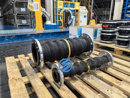
- Non-Standard Machinery Interfaces: To optimize fluid dynamics and maximize internal thermal exchange surface areas, the intake and exhaust ports of modern marine refrigeration plants are engineered with non-standard geometric openings, mandating highly adapted rectangular flange rubber compensator assemblies.
The Engineering Riddle: Why Use Rectangular Flanges on Round Chiller Nozzles?
- Machinery Space Clearance Constraints: Even when the maritime chiller unit fluid nozzle is natively round, tight shipboard structural footprints frequently reject traditional circular flanges.
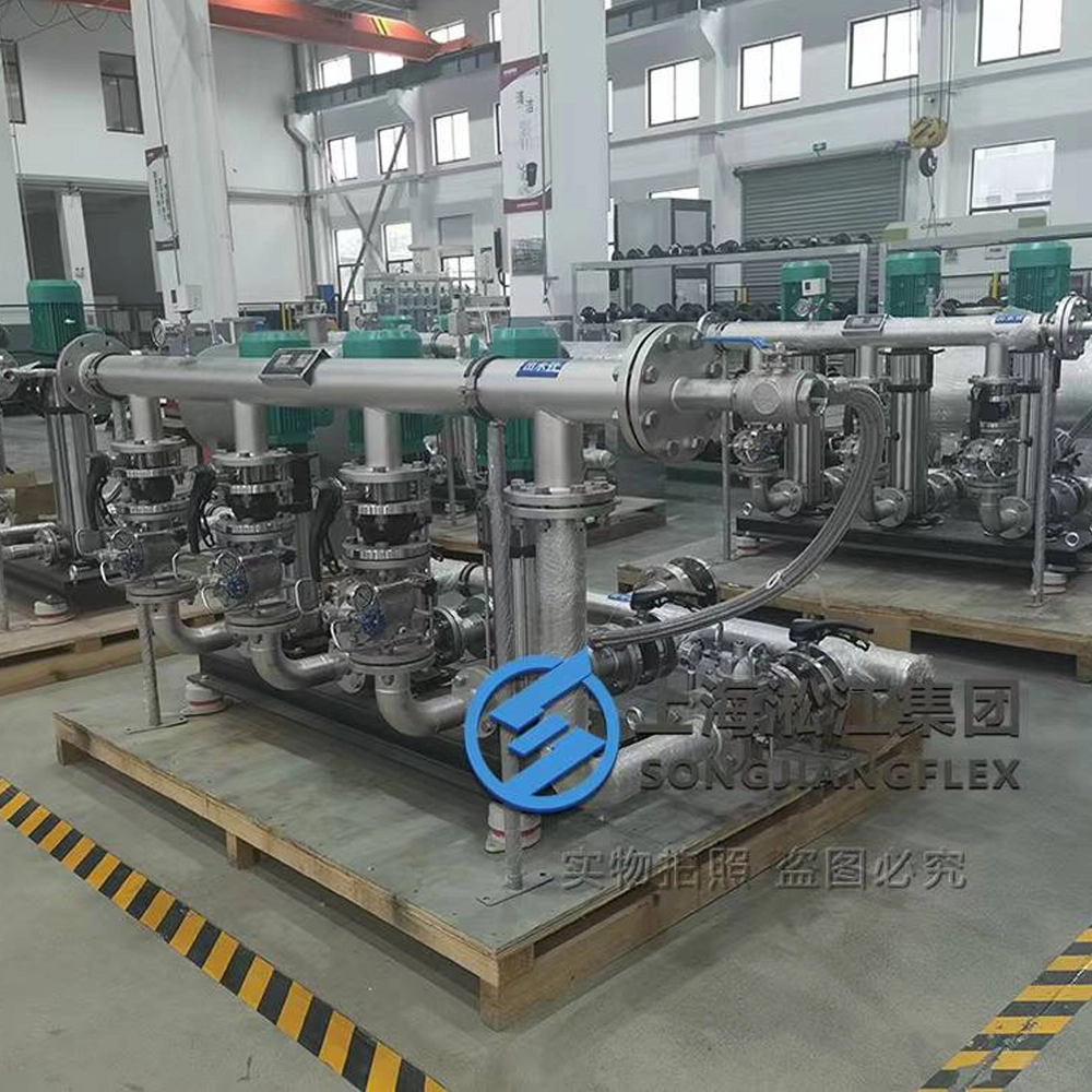
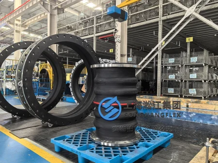
- Integrated Welding Support Brackets: High-end marine piping design utilizes a rectangular flange with integrated welding feet. During one-time shipyard fabrication, these built-in mounting feet are secured directly to the vessel’s foundation steel frames, transforming the heavy-duty rubber compensator into a self-supporting structural anchor.
- Eliminating Secondary Rigid Pipe Hangers: This multi-functional geometry eliminates bulky secondary rigid pipe hangers. It preserves vital millimeter clearance inside compact vessel engine rooms and stops flange perimeters from colliding with structural steel frames, successfully neutralizing severe structure-borne noise.
Why Standard Round Connectors Fail on Custom-Shaped Marine Interfaces
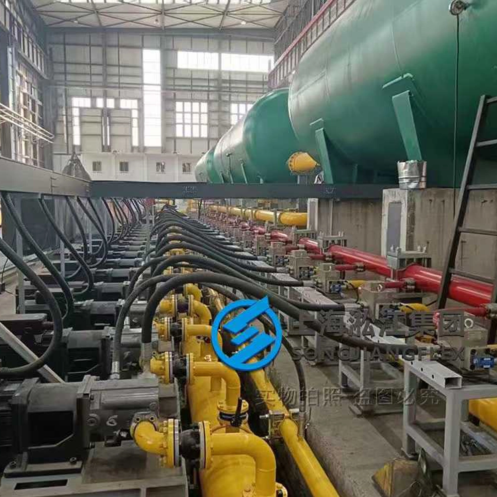
- 1. Lack of Integrated Load-Bearing Supports: Round fittings cannot provide rigid, flat foundation anchoring at the vessel chiller interface. Under heavy open-sea swells, the static weight of the pipe string transfers intense bending moments straight onto the compressor nozzle, inducing catastrophic metal fatigue and weld cracks.
- 2. Structure-Borne Noise & IMO Acoustic Compliance: Rigid metallic piping expansion joints fail to dampen the structural acoustic paths travelling from the compressor to the upper accommodation decks. The high-pitched whine easily bypasses rigid networks, breaching strict shipboard noise boundary limits mandated by the International Maritime Organization (IMO).
- 3. Salt Spray Aggression & Marine Fuel Mist Degradation: Ship bilges inherently pool heavy petroleum vapors, lubricant mists, and hyper-saline oceanic air. Universal industrial connectors break down under this dual-chemical exposure, leading to rubber compound swelling, surface peeling, and complete loss of elastic flexibility.
Strategic Advantages of Dual-Purpose Rectangular Rubber Compensators
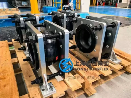
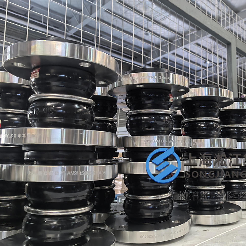
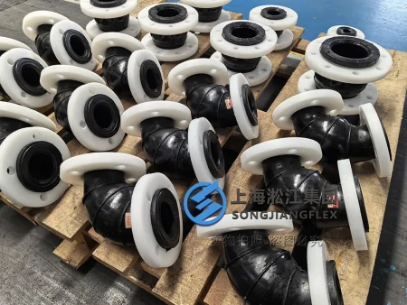
- Load-Bearing Structural Base: This specialized rectangular flange rubber compensator features pre-engineered structural feet. It securely transfers the static pipe weight down to the ship’s hull through its integrated mounting base, shielding the sensitive flexible rubber body from structural shear forces.
- 3-Axis Vibration Isolation: Exploiting the high viscoelasticity of our specialized marine elastomer matrix, these rectangular connectors simultaneously swallow axial, lateral, and angular misalignments induced by ship pitching and rolling, absorbing up to 95% of rigid structure-borne noise.
- Naval Grade Polymeric Matrix: Engineered specifically for harsh maritime applications, the outer rubber shell exhibits immunity to corrosive salt air and oil contamination, while the inner lining stands resilient against continuous high-velocity cooling water scouring.
Strict Engineering Protocol for Rectangular Rubber Compensator Installation
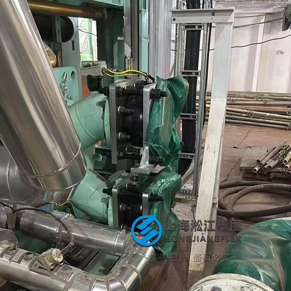
- Step 1: Weld and Anchor the Mounting Feet First: Secure and weld the integrated structural feet of the rectangular flange to the vessel foundation frame. Ensure the load-bearing support is fully anchored before mating the fluid lines to protect the rubber compensator from carrying excessive structural stress.
- Step 2: Align Flange Bolt Circle Precisely: Carefully align the rectangular flange bolt holes with the mating chiller interface. Ensure the pipe string layout is neutral to avoid introducing initial tensile or torsional stress onto the flexible rubber bellows.
- Step 3: Cross-Diagonal Torque Specification: Because rectangular flanges concentrate pressure differently across long edges and sharp 90-degree corners, installers must enforce a multi-stage star torque sequence with a calibrated wrench to prevent localized compression damage to the rubber sealing face.
- Step 4: Critical Adjustment of Control Rods: Rigidly inspect the heavy-duty control rods and limit tie rods assembly. Adjust the locking nuts to precise design tolerances to ensure the rubber compensator can fully absorb high-frequency vibration while preventing dangerous over-elongation or pressure-surge blowouts during extreme open-sea navigation.