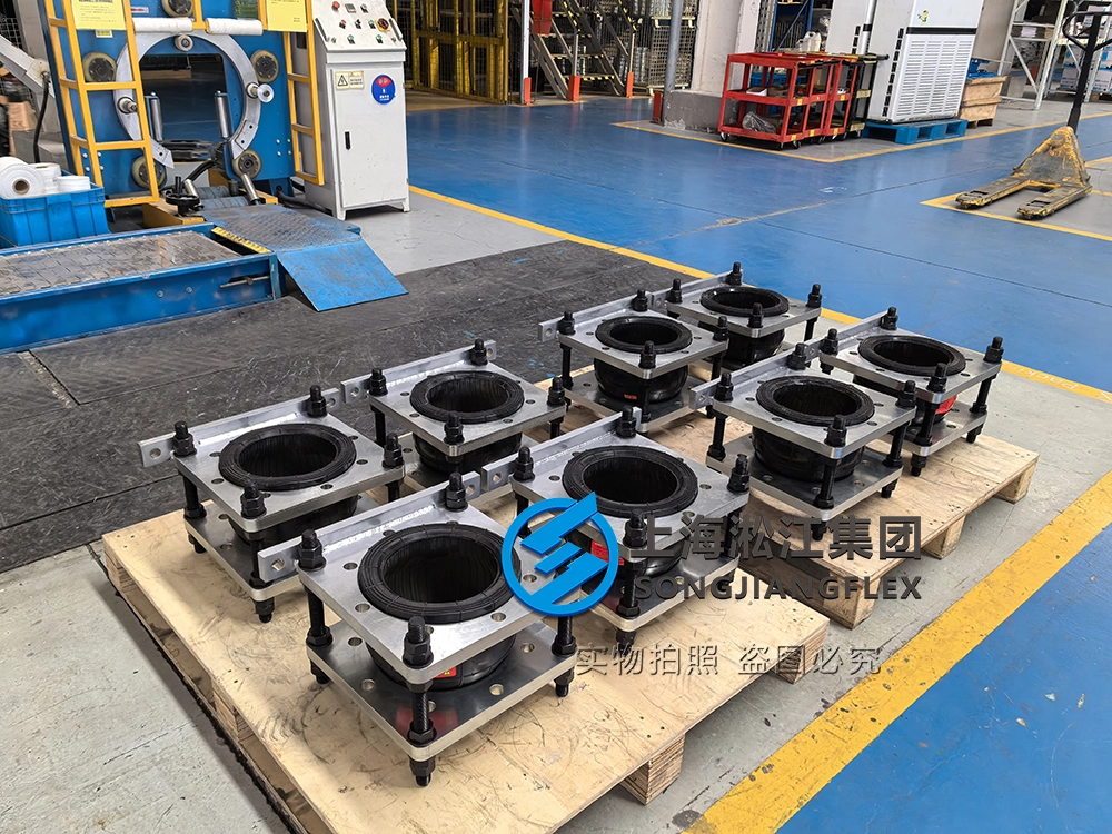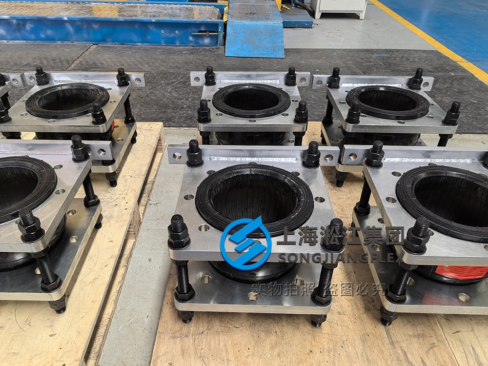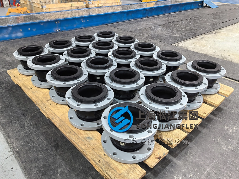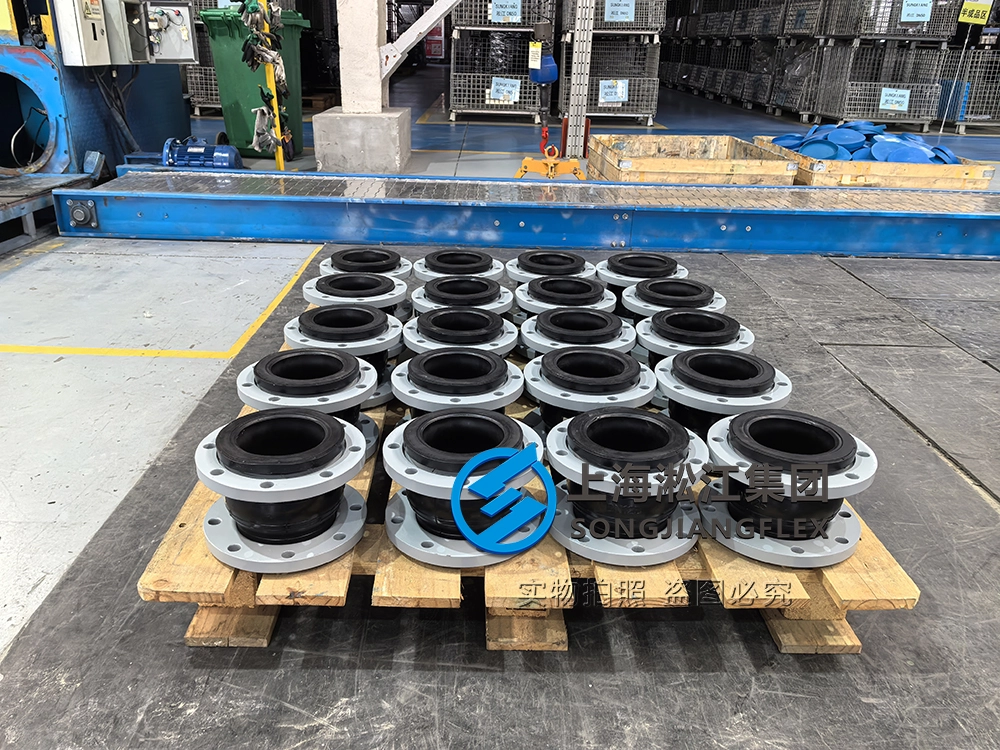
Vacuum-Resistant Rubber Compensator with PTFE Liner for DN1200 Flue Gas Pipelines
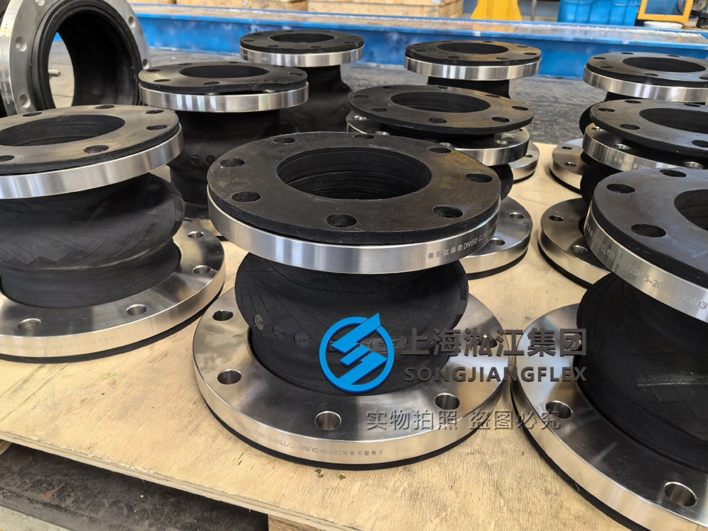
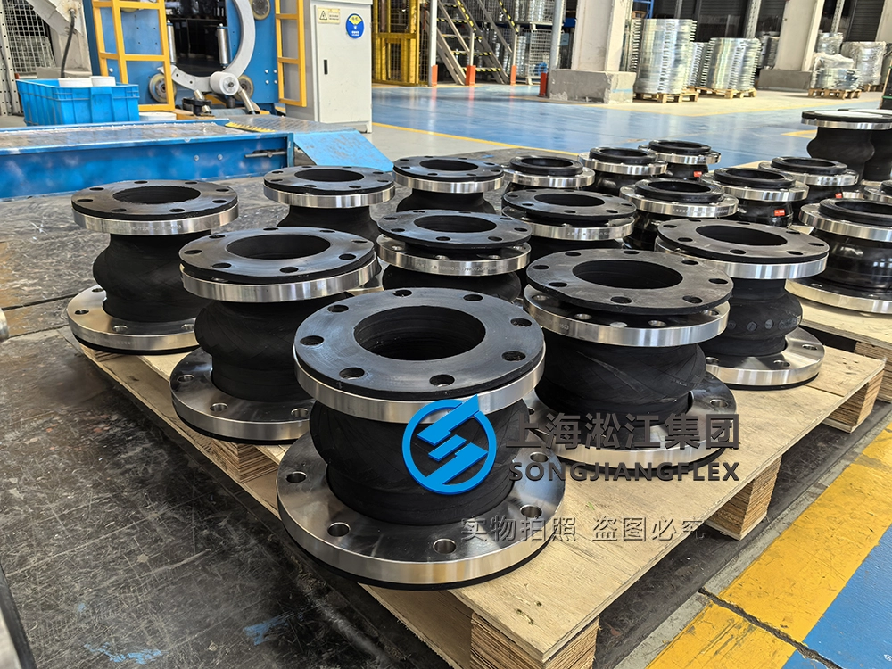
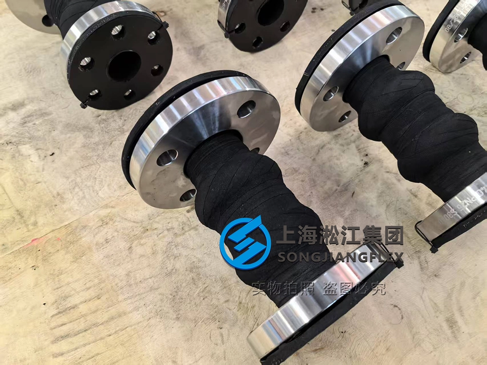
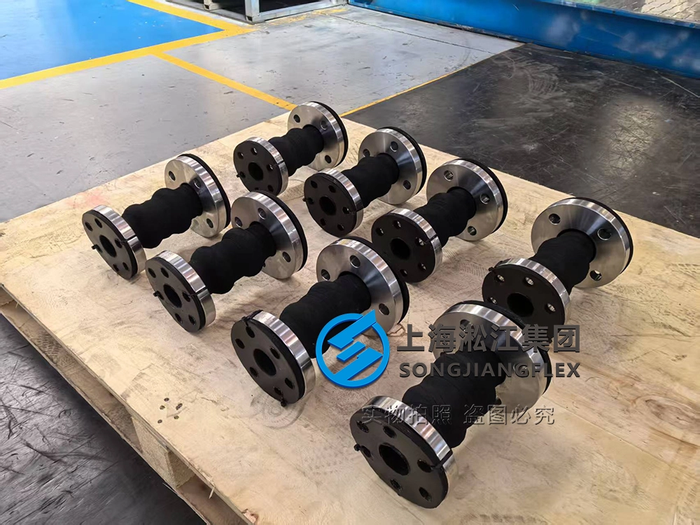
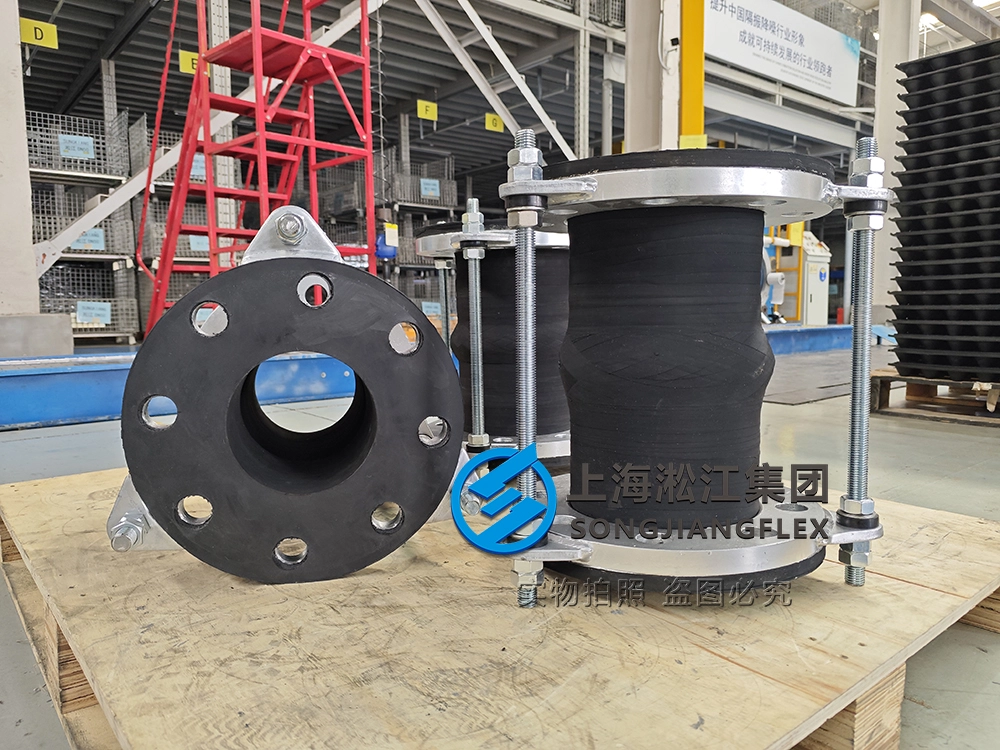
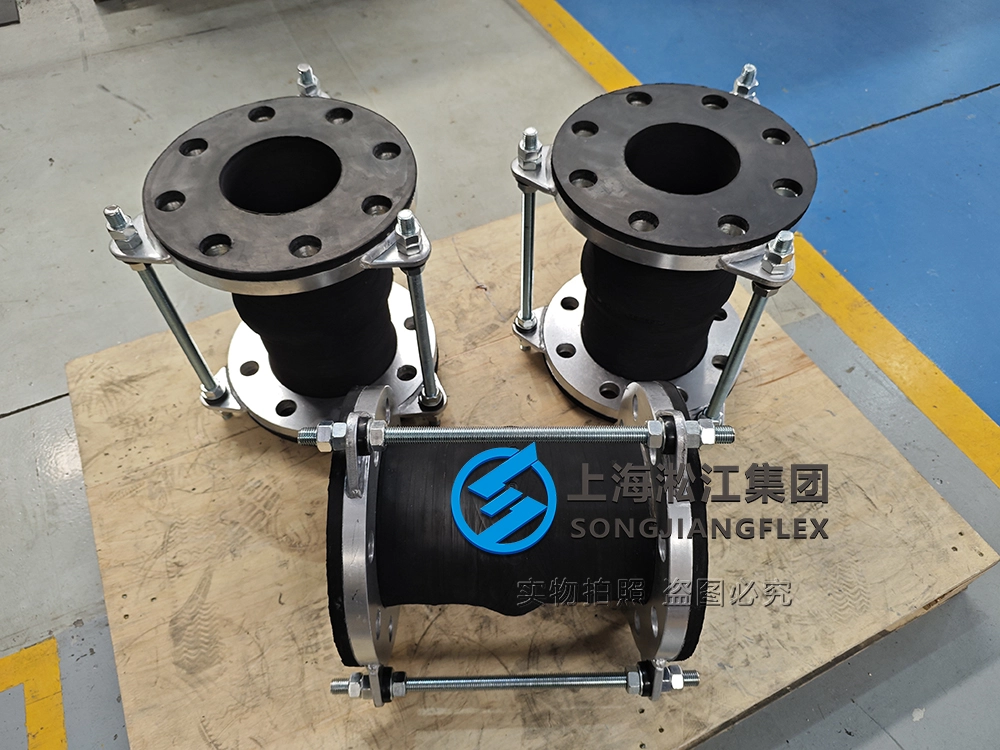
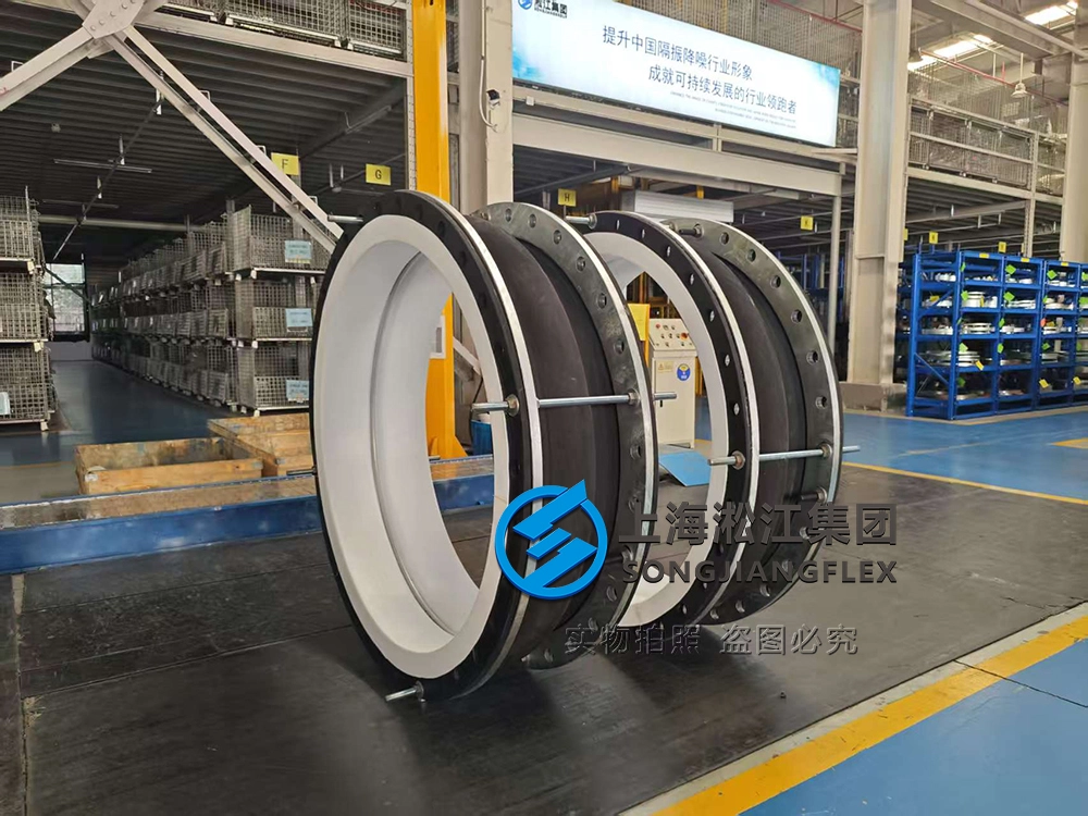
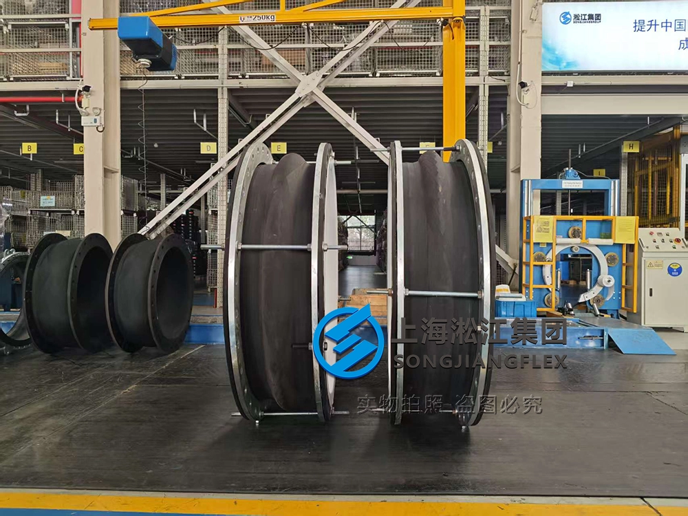
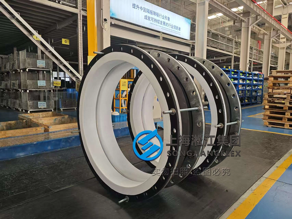
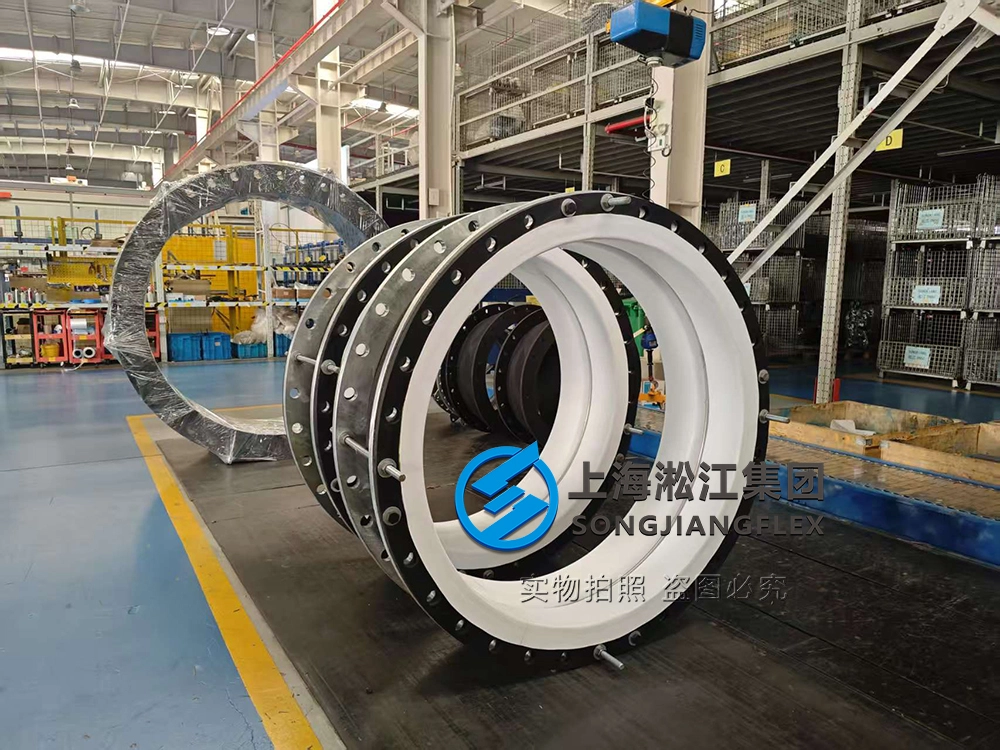
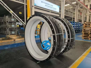
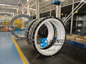
This DN1200 hand-built single-arch rubber compensator is a flexible piping component engineered with a Hypalon elastomeric matrix and a continuous, bonded PTFE internal liner (thickness ≥3mm). The single-convolution geometry is built within a 400mm laying length to maintain the bellows profile while accommodating piping displacements.
The structural design addresses the risk of polymer chemical degradation and geometric buckling under negative pressure in gas exhaust systems. By incorporating a vacuum support ring behind the PTFE liner, the assembly prevents the vacuum-induced collapse of the fluoropolymer layer.
This component is designed for exhaust lines handling fluorine-containing gases, operating within a temperature range of -20°C to 90°C, a positive working pressure of 0.1 MPa, and a negative pressure of -0.91 bar.
The ≥3mm PTFE liner isolates the load-bearing Hypalon carcass from direct contact with the fluorine-containing flue gas. This material separation prevents chemical permeation and subsequent swelling of the elastomer matrix under the specified operating parameters; actual field life remains subject to specific operating conditions.
Key Engineering Features
- Integrated ≥3mm PTFE Liner – isolates the load-bearing Hypalon rubber carcass from direct gas contact, preventing elastomer swelling and chemical degradation from fluorine-containing exhaust components.
- PTFE-Lined Vacuum Support Ring – provides a structural backup skeleton to the internal fluoropolymer layer, preventing the liner from flattening or collapsing under negative pressures down to -0.91 bar.
- Full Face Sealing Profile – extends the combined Hypalon body and PTFE liner continuously over the entire flange face, utilizing the component materials as the sealing interface to eliminate separate gasket leak paths.
- Integral Control Unit Limit Rods – restricts axial extension within the specified design limits and controls structural displacement under a positive working pressure of 0.1 MPa.
- Hot-Dip Galvanized S235 Carbon Steel Flanges (HG/T 20592 / PN16) – provides rigid structural bolting rings rated for PN16 pressure classification that resist atmospheric oxidation and ensure uniform torque distribution across the DN1200 mating interface.
Applications
- Industrial Fluorine-Containing Exhaust Ducts – absorption of thermal displacement and mechanical vibration in large-diameter gas transfer mains handling acidic scrubbing vapors.
- Chemical Plant Acid Flue Gas Handling Systems – installation on the suction and discharge lines of industrial fans operating under concurrent low-pressure and negative-pressure cycles.
- Corrosive Process Ventilation Piping – decoupling of dynamic equipment vibrations from rigid external piping runs crossing industrial processing facility foundations.
Technical FAQ
Q: How do the vacuum support ring and the limit rods operate under concurrent positive pressure and negative pressure cycles in a DN1200 rubber compensator?
A: At a nominal diameter of DN1200, the component must transition between a positive working pressure of 0.1 MPa and a negative pressure boundary of -0.91 bar. Under the negative pressure cycle, a radial differential pressure load is created across the joint wall, introducing a risk of structural buckling. The vacuum support ring serves as a rigid mechanical backup skeleton that directly resists this inward radial pressure drop, ensuring the assembly maintains the flow passage geometry and preventing the PTFE layer from collapsing inward.
When the system switches to the positive working pressure of 0.1 MPa, the pressure generates thrust forces that tend to elongate the bellows axially. The integral control unit limit rods restrict axial extension within the specified design limits, preventing excessive elongation of the single-arch profile while remaining subject to actual operating conditions for exact load distribution.